
Knowledge of drilling equipment--Drilling fluid solid control system and tools 1
2024-01-19 10:00Drilling fluid solid control system and tools
Concept: Drillidrilling fluidng fluid solid phase control is to remove the harmful solid phase in the drilling fluid and preserve the useful solid phase to meet the requirements of the drilling technology for the performance of the drilling fluid. Drilling fluid solid phase control system is the general term of all drilling fluid solid phase control equipment.
Function: Prevent the blockage and destruction of oil and gas channels, reduce drilling torque and friction, reduce the pressure fluctuation of annular suction, increase drilling speed, prolong the life of the drill bit, and reduce the wear and tear of equipment.
Methods: There are four commonly used methods: dilution method, substitution method, mechanical method, and chemical method. The mechanical method is to use the principles of screening, centrifugal separation, gravity separation, etc., through mechanical equipment, the solid phase components in the drilling fluid are separated according to the different particles and densities, so as to achieve the purpose of controlling the solid phase.
The development process of drilling fluid solid control system: before the 50s of the 20th century, no mechanical device was used to purify the drilling fluid, and after the 50s of the 20th century, the drilling fluid vibrating screen and centrifuge were used to remove the cuttings in the drilling fluid. After the 60s, foreign oilfields began to use 4-inch desilting cyclone separators, and in the mid-60s, fine-mesh drilling fluid vibrating screens were used. After the 70s, ultra-fine vibrating screens were used. After the 80s, the solid phase control of drilling fluid has developed from two-stage treatment to three-stage, four-stage and five-stage treatment
Circulating procedure of drilling fluid in drilling: the drilling fluid tank is pumped → ground manifold → riser→ water hose belt, faucet → drill string → drill bit→ outer annular space of drill string→ wellhead, mud (drilling fluid) tank→ drilling fluid purification equipment → drilling fluid tank.
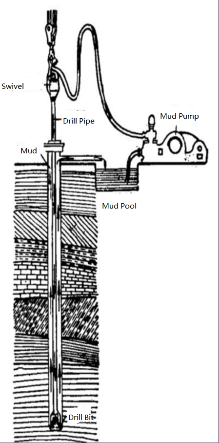
Schematic diagram of the circulation process of a drilling fluid
The drilling fluid from the wellhead flows into the distributor through the pipeline, and is transported to two vibrating screens respectively or at the same time, and enters the sand sinking bin after treatment, and enters the sand removal bin through the crossing pipe. The sand removal pump sucks in the drilling fluid of the sand removal bin, and the drilling fluid enters the desand bin through the transition tank. The desilting pump sucks in the drilling fluid of the desilting chamber, and the drilling fluid enters the centrifugal chamber through the aqueduct.
The vertical liquid supply pump of the centrifuge sucks the drilling fluid from the centrifuge chamber, and the drilling fluid enters the reservoir through the transition tank. The drilling pump sucks the drilling fluid into the reservoir and transports it to the wellhead through the pipeline. In this way, the circulation of the drilling fluid is completed.
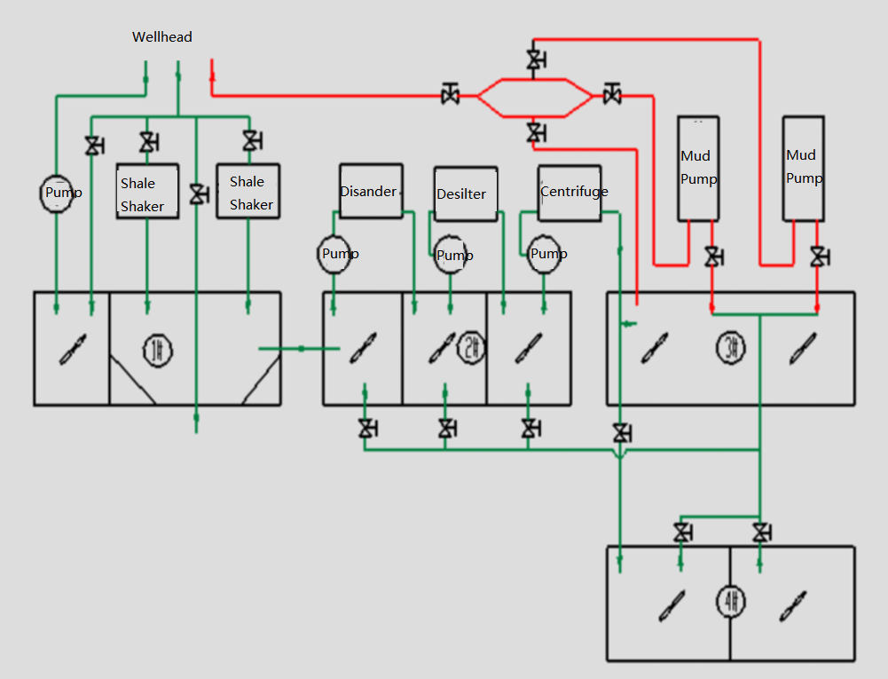
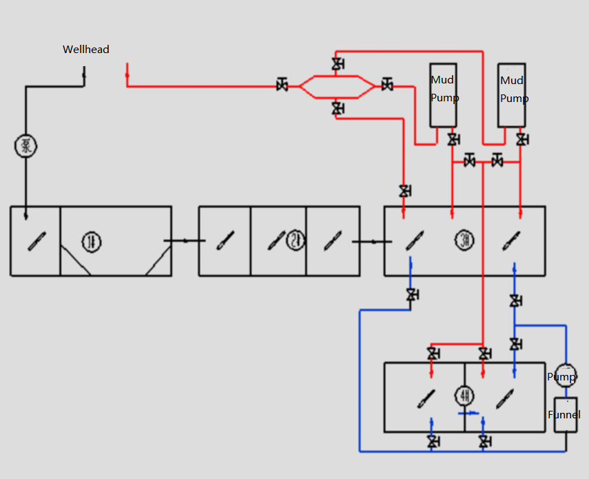
Schematic diagram of a drilling fluid weighting process
The drilling fluid weighting process is an auxiliary process in the process of drilling fluid solid control system. Barite and other components are added to the drilling fluid to increase the density of the drilling fluid and keep the wellbore stable to meet the drilling requirements. The weighted pump of the 4# tank can directly suck the drilling fluid in the drug mixing bin, the weighted mixing bin and the reserve bin through the weighted suction pipeline, and after passing through the weighting funnel weighting place, it will be transported to the 3# tank and 4# tank through the weighted discharge pipeline. This completes the drilling fluid weighting process.
Schematic diagram of a drilling fluid weighting process.
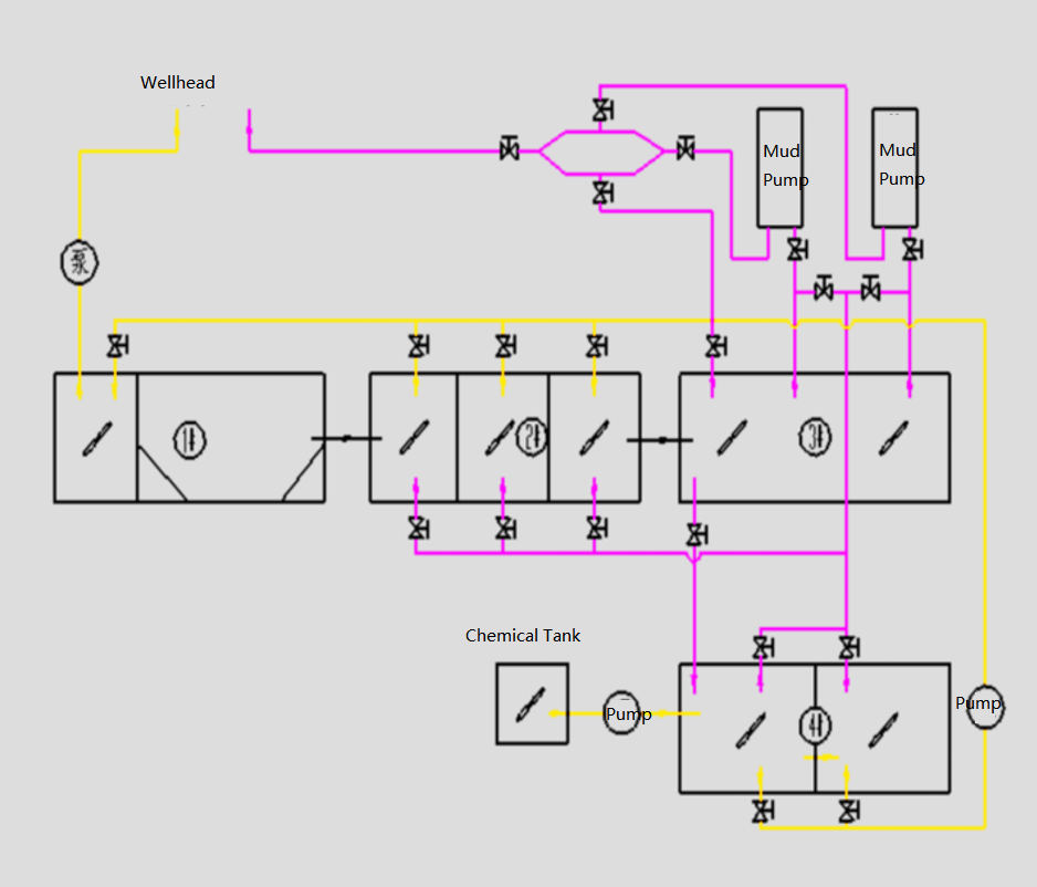
Schematic diagram of a drilling fluid dosing process
The drilling fluid dosing process is to add chemical treatment agent to the drilling fluid, use the principle of chemical sedimentation, remove harmful solid components to improve the performance of drilling fluid, improve the stability of the wellbore, and improve the mechanical rate of penetration. The upper part of the 4# tank drug mixing bin is provided with a dosing tank, and the drug enters the drug mixing bin through the pipeline from the dosing tank, and after stirring and mixing through the agitator, it is transported to the wellhead by the drilling pump through the suction pipeline. It can also be sucked in by the weighted pump through the weighted suction pipeline, and then transported to the 1# tank supply bin, 2# tank and 3# tank through the mud gun pipeline. This completes the drill well fluid dosing engineering.
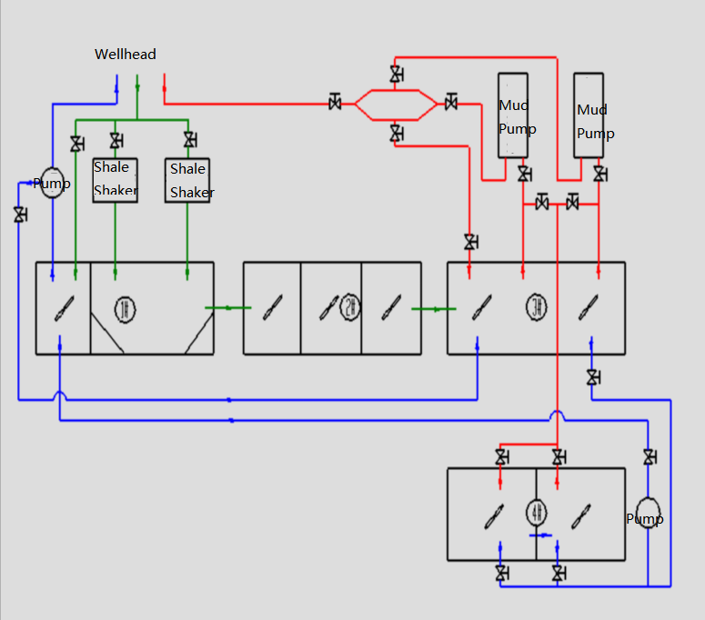
Schematic diagram of a drilling fluid replenishment process
The drilling fluid replenishment process is to ensure the stability of the wellbore by adding drilling fluid to the wellbore in the process of lifting the drilling tool. The left end of the 1# tank is equipped with a supply bin, and the supply pump sucks the drilling fluid from the supply bin and transports it to the wellhead through the discharge pipeline, and the drilling fluid returned from the wellhead enters the supply bin through the valve of the distributor branch. The drilling fluid in the supply bin can also be sucked into the drilling fluid in the storage bin through the weighted pump, and transported to the supply bin through the mud gun pipeline. This completes the drilling fluid replenishment process.
.
