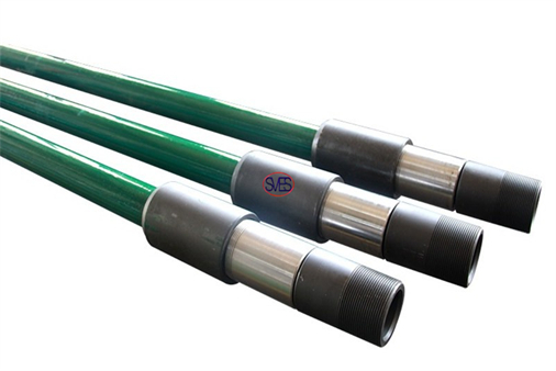
SVES Oilfield Supply Co., Ltd Tubing Pump
2023-12-27 10:00SVES Oilfield Supply Co., Ltd Tubing Pump
The TH tubing pumps feature heavy-walls and full-barrels.
These pumps can be assembled with:
•Box-end and pin-end plungers;
•Cup-type or mechanical seating assemblies;
•Tap-type or lock-type, standing-valve pullers;
All-metal, heavy-wall-barrel tubing pumps combine heavy-duty construction and a stroke-through design with the largest bore possible for any given tubing size to maximize production.
The one-piece barrel eliminates joints susceptible to failure under working loads and is precision honed from end to end to ensure a perfect bore for the plunger and increase pumping efficiency.
Structural Characteristics:

The tubing pump is structurally robust and consists of pump barrel plunger, an oil drain (optional), standing valve, and extension nipple.
The pump barrel is installed at the bottom of the tubing, the standing valve is installed under the pump barrel, the plunger is connected to the sucker rod, and the entire plunger is placed in the pump barrel, above the standing valve.
Working Principle:
When the pumping unit is in motion, the sucker rod and the plunger are driven to reciprocate linearly in the pump barrel to recovery oil.
When the plunger is running on the stroke, under the action of the gravity of the liquid column in the oil pipe, the traveling valve is closed, and the pressure in the pump barrel below the plunger is lowered, and the standing valve is opened under the action of the oil pressure in the annular cavity of the casing.
The oil enters the cavity created by the upward movement of the plunger.
When the plunger is stroked down, the standing valve is closed, and the pressure inside the pump barrel under the plunger increases.
The traveling valve is opened, so that when the plunger is stroked, the well fluid passing through the standing valve passes through the cavity of the traveling valve and the plunger during the down stroke, into the annular cavity between the sucker rod and the oil pipe above the plunger.
On the next upstroke, these well fluids are lifted together with the remaining well fluid in the annular cavity of the tubing and sucker rods. In fact, only the upstroke is lifted.
| Pump code | 25-106TH | 25-125TH | 25-150TH | 25-175TH | 25-200TH | 25-225TH | 30-250TH | 30-275TH | 40-325TH | 40-375TH |
| Basic pump diameter | 1 1/16 | 1 1/4 | 1 1/2 | 1 3/4 | 2 | 2 1/4 | 2 1/2 | 2 3/4 | 3 1/4 | 3 3/4 |
| -27 | -31.8 | -31.8 | -44.5 | -50.8 | -57.2 | -63.5 | -69.9 | -82.6 | -95.3 | |
| Plunger length | ≤26(7925) | |||||||||
| Pump barrel length | ≤34(10363) | |||||||||
| Stroke ft (mm) | ≤32(9754) | |||||||||
| Connecting tubing thread | 2 7/8 NU(EU) | 3 1/2 NU(EU) | 4NU | 4EU | ||||||
| Connecting sucker rod thread | 3/4 in | 7/8 in | 1 in | |||||||
| Theoretical displacement | 0.824 sn | 1.140 sn | 1.642 sn | 2.235 sn | 2.918 sn | 3.694sn | 4.560 sn | 5.518 sn | 7.707 sn | 10.261 sn |
| Maximum outer diameter (mm) | 3.5 | 3.5 | 3.5 | 3.5 | 3.5 | 3.5 | 4.25 | 4.25 | 4.5 | 4.6 |
| -88.9 | -88.9 | -88.9 | -88.9 | -88.9 | -88.9 | -108 | -108 | -114.3 | -117 | |
Applicable condition:
1.Sand content in well fluid ≤0.2%
2.he total salinity dissolved in the well fluid does not exceed 10000mg/L or the chloride does not exceed 6000mg/L, the hydrogen sulfide content is less than 10ppm, and the carbon dioxide contTubing Pump ent is less than 250ppm.
3.Gas-liquid ratio ≤60m3/m3, well deviation ≤30°
4.Ban touching pumps
