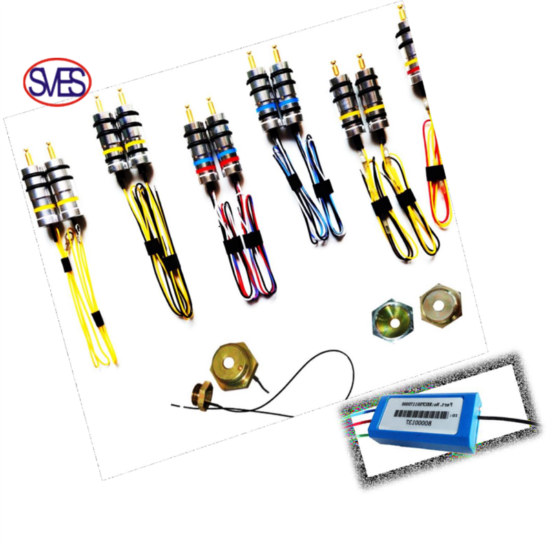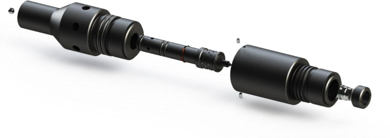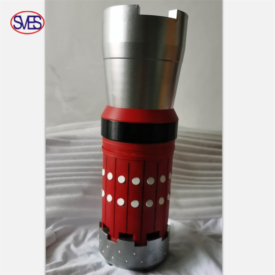
Horizontal Well Composited Perforation Assembly
SELECTIVE PERFORATING
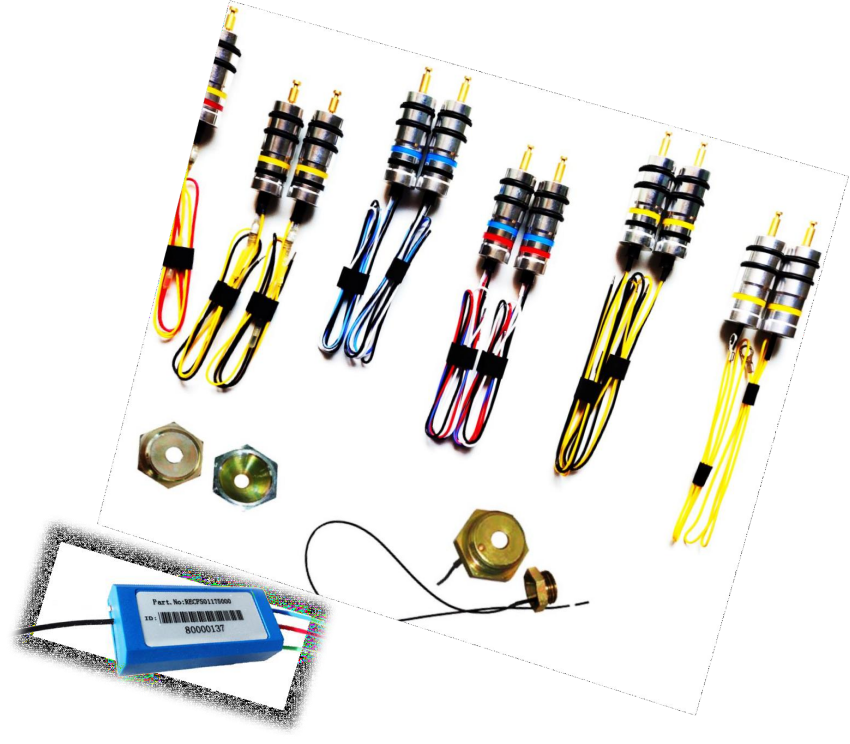
DDPS Positive (+) Dual Diode Switch
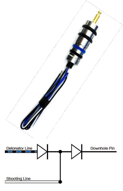
Technical Information
Shooting line color: White Detonator line color: Black/Blue Ground line color(Optional): Black Downhole pin: Brass pin
Max. Pressure: 15,000 psi (103 MPa) Max. Temp.: 177°C(350°F)
Max. Voltage : 600 VDC Max. Current : 2,000 mA
INSTRUCTION
Dual Diode Switch is installed in bulkhead body. It can pass positive (+) current to detonator in lower gun and negative (-) current to detonator in upper gun.
The polarity of the upper and lower detonator connections cannot be changed by the operator. The white wire on a dual diode must always be connected to the shooting line. If the upper detonator and shooting line are reversed, both detonators will be fired at once.
INSPECTION METHODS
ELECTRICAL INSPECTION | From | To | Multimeter Reading |
White wire (+ polarity) | Downhole pin (- polarity) | 0.5-0.7 V | |
White wire (+ polarity) | Blue wire (- polarity) | ∞ V | |
White wire (- polarity) | Blue wire (+ polarity) | 0.5-0.7 V | |
White wire (- polarity) | Downhole pin (+ polarity) | ∞ V | |
Downhole pin | Switch (or gun) body | > 20 MΩ | |
MECHANICAL INSPECTION | Ensure O-rings (size 113), switch body, downhole pin and wiring insulation show no signs of damage. It is not recommended to pull or twist on anything (excessive pulling will damage the switch). | ||
DDNS Negative(-)Dual Diode Switch
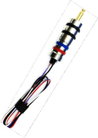
Technical Information
Shooting line color: White Detonator line color: Red/Blue Ground linecolor(Optional): Black Downhole pin: Brass pin
SPECIFICATIONS
Part Number: SFSwitch-DDNS
Max. Pressure: 15,000 psi (103 MPa)
Max. Temp.: 177°C(350°F)
Max. Voltage : 600 VDC Max.
Current : 2,000 mA
INSTRUCTION
Dual Diode Switch is installed in bulkhead body. It can pass negative (-) current to detonator in lower gun and positive (+) current to detonator in upper gun.
The polarity of the upper and
lower detonator connections cannot be changed by the operator. The white wire on a dual diode must always be connected to the shooting line. If the upper detonator and shooting line are reversed, both detonators will be fired at once.
INSPECTION METHODS
ELECTRICAL INSPECTION | From | To | Multimeter Reading |
White wire (- polarity) | Downhole pin (+ polarity) | 0.5-0.7 V | |
White wire (- polarity) | Red wire (+ polarity) | ∞ V | |
White wire (+ polarity) | Red wire (- polarity) | 0.5-0.7 V | |
White wire (+ polarity) | Downhole pin (- polarity) | ∞ V | |
Downhole pin | Switch (or gun) body | > 20 MΩ | |
MECHANICAL INSPECTION | Ensure O-rings (size 113), switch body, downhole pin and wiring insulation show no signs of damage. It is not recommended to pull or twist on anything (excessive pulling will damage the switch). | ||
PPS Positive (+) Pressure Switch
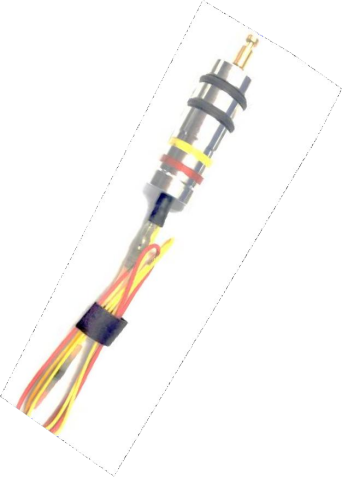
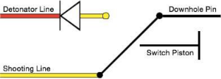
Technical Information
Shooting line color: Yellow Detonator line color: Red Downhole pin: Brass pin
SPECIFICATIONS
Part Number: SF Switch-PPS
Max. Pressure: 15,000 psi (103 MPa)
Max. Temp.: 177°C(350°F)
Max. Voltage : 600 VDC Max.
Current : 2,000 mA
INSTRUCTION
Pressure shock wave actuated positive switch will pass positive (+) current to the detonator but will block negative (-) current from the detonator.
INSPECTION METHODS
ELECTRICAL INSPECTION | From | To | Multimeter Reading |
Yellow wire | Downhole pin | < 1 Ω | |
Yellow wire | Switch (or gun) body | > 20 MΩ | |
Yellow wire (both polarities) | Red wire | > 20 MΩ | |
Red wire (both polarities) | Switch (or gun) body | > 20 MΩ | |
MECHANICAL INSPECTION | Ensure O-rings (size 113), switch body, downhole pin and wiring insulation show no signs of damage. It is not recommended to pull or twist on anything (excessive pulling will damage the switch). | ||
PNS Negative (-) Pressure Switch
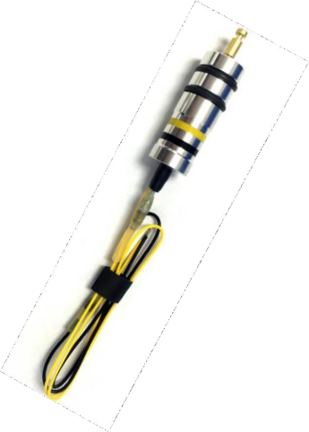
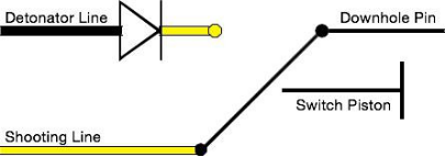
Technical Information
Shooting line color: Yellow Detonator line color: Black Downhole pin: Brass pin
SPECIFICATIONS
Part Number: SF Switch-PNS
Max. Pressure: 15,000 psi (103 MPa)
Max. Temp.: 177°C(350°F)
Max. Voltage : 600 VDC
Max. Current : 2,000 mA
INSTRUCTION
Pressure shock wave actuated positive switch will pass positive (+) current to the detonator but will block
negative (-) current from the detonator.
INSPECTION METHODS
ELECTRICAL INSPECTION | From | To | Multimeter Reading |
Yellow wire | Downhole pin | < 1 Ω | |
Yellow wire | Switch (or gun) body | > 20 MΩ | |
Yellow wire (both polarities) | Black wire | > 20 MΩ | |
Black wire (both polarities) | Switch (or gun) body | > 20 MΩ | |
MECHANICAL INSPECTION | Ensure O-rings (size 113), switch body, downhole pin and wiring insulation show no signs of damage. It is not recommended to pull or twist on anything (excessive pulling will damage the switch). | ||
Thru-Wire /No Grounding
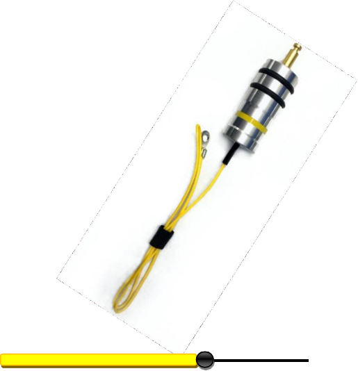
Gun shooting line Downhole Pin
Technical Information
Shooting line color: Yellow (or follow customer require) Downhole pin: Brass pin
SPECIFICATIONS
Part Number: SF Switch-YE
Max. Pressure: 20000 psi (140 MPa)
Max. Temp.: 177°C(350°F)
Max. Voltage : 600 VDC
Max. Current : 2,000 mA
INSTRUCTION
Gun shooting line Downhole Pin
INSPECTION METHODS
ELECTRICAL INSPECTION | From | To | Multimeter Reading |
Yellow wire | Downhole pin | < 1 Ω | |
Yellow wire |
Switch Body |
>10M Ω |
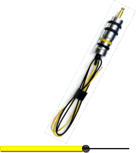
Thru-Wire /Grounding

Technical Information
Shooting line color: Yellow (or follow customer require) Ground line color(Optional): Black(or follow customer require) Downhole pin: Brass pin
SPECIFICATIONS
Part Number: SF Switch-YEGD
Max. Pressure: 20000 psi (140 MPa)
Max. Temp.: 177°C(350°F)
Max. Voltage : 600 VDC
Max. Current : 2,000 mA
INSTRUCTION & INSPECTION METHODS
ELECTRICAL INSPECTION | From | To | Multimeter Reading |
Yellow wire | Downhole pin | < 1 Ω | |
Black wire | Switch Body | < 1 Ω | |
Yellow wire | Switch Body | >10M Ω |
Retainer Nuts
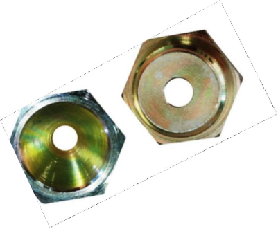
Inner Diameter: ¼’’
Use with Feed Thru Switch, Pressure Switch or Dual Diode Switch
Prevents an upper gun from comprising a tool below
Retainer Nuts with Ground
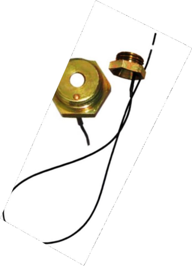
Inner Diameter: ¼’’
Ground wire attached. Use with Feed Thru Switch,
Pressure Switch or Dual Diode Switch Prevents an upper gun from comprising a tool below
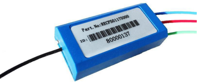
E-Addressable Switch
SPECIFICATIONS | |
P.N. | RECFS01175000 |
Max. Temp. | 347℉ (175℃) |
Operating Voltage Rating | -5~550 VDC |
Operating Current | 1~2mA |
Operating Current(Communicating) | 3mA(Surface) |
27mA(Downhole) | |
Max switchs in a Gun String | 50 |
Downhole SPECIFICATIONS | |
Maximum Voltage Rating | 500V |
Maximum Firing Current | 2A |
E-Addressable Switch Line Color Instruction
GREEN : To Detonator Negative Wire
RED : To Detonator Positive Wire
BLUE: To Next Gun
BLACK: To The Ground
WHITE: To Upper Gun
Control Panel
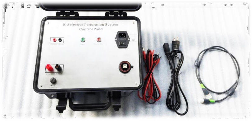
⚫ Perforating command and control panel connects the shooting panel and wireline
⚫ Fully automated software drivepanel
⚫ Relay disconnect when switch communications are not In progress
⚫ On/off key for power off confirmation
⚫ Gun communication limits
⚫ Input Voltage: AC100 ~240V, 50Hz
⚫ Output Voltage: 0 ~ 36V
⚫ Output Current: <200mA
⚫ Connect Switch Quantity: 1 ~ 50
⚫ Size:323mm×275mm×135mm
Test Panel
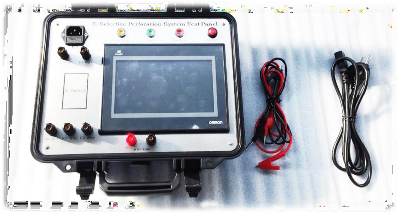
⚫ Test the whole gun string on the surface before attaching to the wireline
⚫ Perform the switch safety checks and reports failed switch test
⚫ User friendly graphical interface
⚫ Improve confidence before running inhole
⚫ Limited current to ensure non-firing if load with detonator
⚫ Battery power supply
⚫ Working Temperature: -10℃~+50℃
⚫ Input Power: 100V~240V AC
⚫ Max test switch quantity: 50
Firing Head
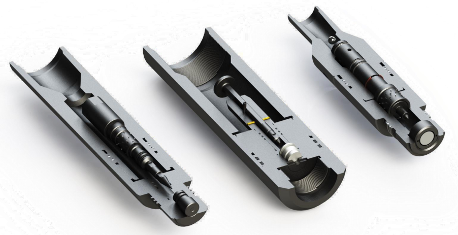
Quick change Electric detonator firing head
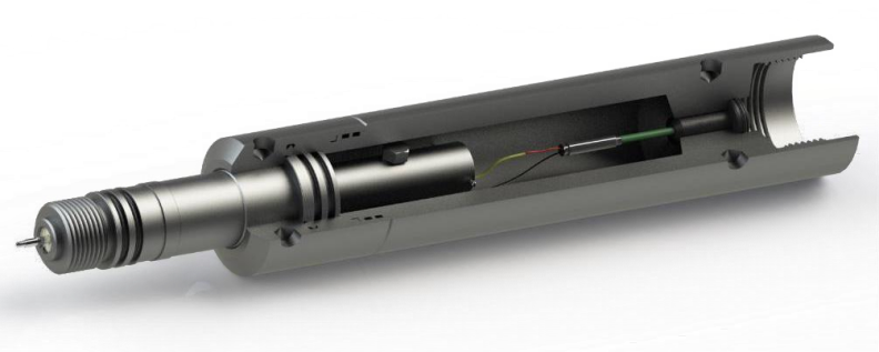
Technical Information
Item | Description |
Connect thread upper |
1 5/8-6Acme(P) |
Connect thread bottom |
2 3/4-6Acme(B) |
OD |
79.375mm(3.125in) |
Length |
530mm(20.8in) |
Max Pressure |
10150 psi(70 MPa) |
Max Temperature |
Depend On the explosives |
Maximum Tensile Strength |
45000 lbf(200 KN) |
Drop Ball Pressure-activated Vent Firing Head
Technical Information
Item | Description | ||||
TYPE | 2(50.8mm) | 2-3/8in(60.3mm) | 2-7/8in(73.0mm) | 3-1/2in(88.9mm) | |
| O.D. MAX |
86mm |
80mm | 3.661in (93mm) | 4.500in (114.3mm) | |
Overall Length | 412mm | 422mm | 432mm | 442mm | |
Connection | Upper Thread | 1.5AMMT BOX | 2-3/8 EU BOX | 2-7/8 EU BOX | 3-1/2 EU BOX |
Bottom Thread | 2 3/4-6ACME BOX | 2 3/4-6ACME BOX | 2 3/4-6ACME BOX | 2 3/4-6ACME BOX | |
Max Temp | Depend On Detonator | ||||
Detonator | DYNA | ||||
Max Pressure | 126MPa | ||||
Additional Instructions:
Body Material: 4140
O-ring Material: Viton-70 Durometer
Direct Pressure Firing Head
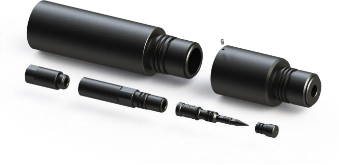
Technical Information
Item | Description | |||
TYPE | 2-3/8in(60.3mm) | 2-7/8in(73.0mm) | 3-1/2in(88.9mm) | |
| O.D. MAX | 80mm | 93mm | 114.3mm | |
Overall Length | 528.5mm | 528.5mm | 528.5mm | |
Connection | Upper Thread | 2-3/8 EU BOX | 2-7/8 EU BOX | 3-1/2 EU BOX |
Bottom Thread | 2 3/4-6ACME BOX | 2 3/4-6ACME BOX | 2 3/4-6ACME BOX | |
Max Temp | 200℃ | |||
Detonator | DANY | |||
Max Pressure | 137.9MPa | |||
Additional Instructions
Body Material: 4140
O-ring Material: Viton-70 Durometer
Mechanical Firing Head
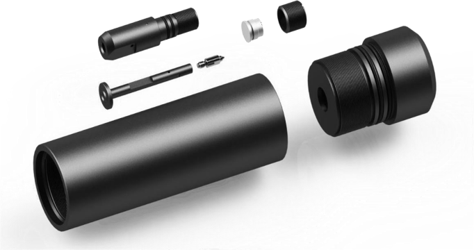
Technical Information
Item | Description | |||
TYPE | 2-3/8in(60.3mm) | 2-7/8in(73.0mm) | 3-1/2in(88.9mm) | |
| O.D. MAX | 80mm | 93mm | 114.3mm | |
Overall Length | 528.5mm | 528.5mm | 528.5mm | |
Connection | Upper Thread | 2-3/8 EU BOX | 2-7/8 EU BOX | 3-1/2 EU BOX |
Bottom Thread | 2 3/4-6ACME BOX | 2 3/4-6ACME BOX | 2 3/4-6ACME BOX | |
Max Temp | 200℃ | |||
Detonator | DANY | |||
Max Pressure | 137.9MPa | |||
Additional Instructions
Body Material: 4140
O-ring Material: Viton-70 Durometer
Drop Bar Pressure-activated Firing Head
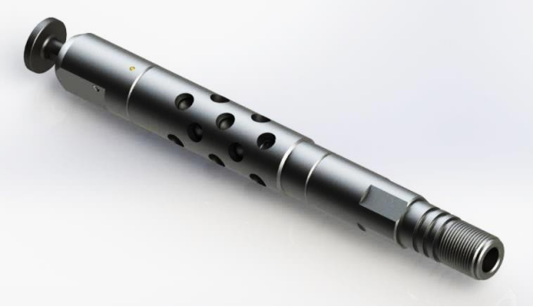
Technical Information
Item | Description | |
| O.D. MAX | 35mm | 35mm |
Overall Length | 385mm | 385mm |
Min. Required Hydrostatic | 200psi | 2000psi |
Max. Operating Pressure | 8500psi | 20000psi |
Max Temp | 200℃ | |
Detonator | DYNA | |
Additional Instructions
Body Material: 4140
O-ring Material: Viton-70 Durometer
