- Home
- >
- Products
- >
- Sucker Rod Pump
- >
Sucker Rod Pump
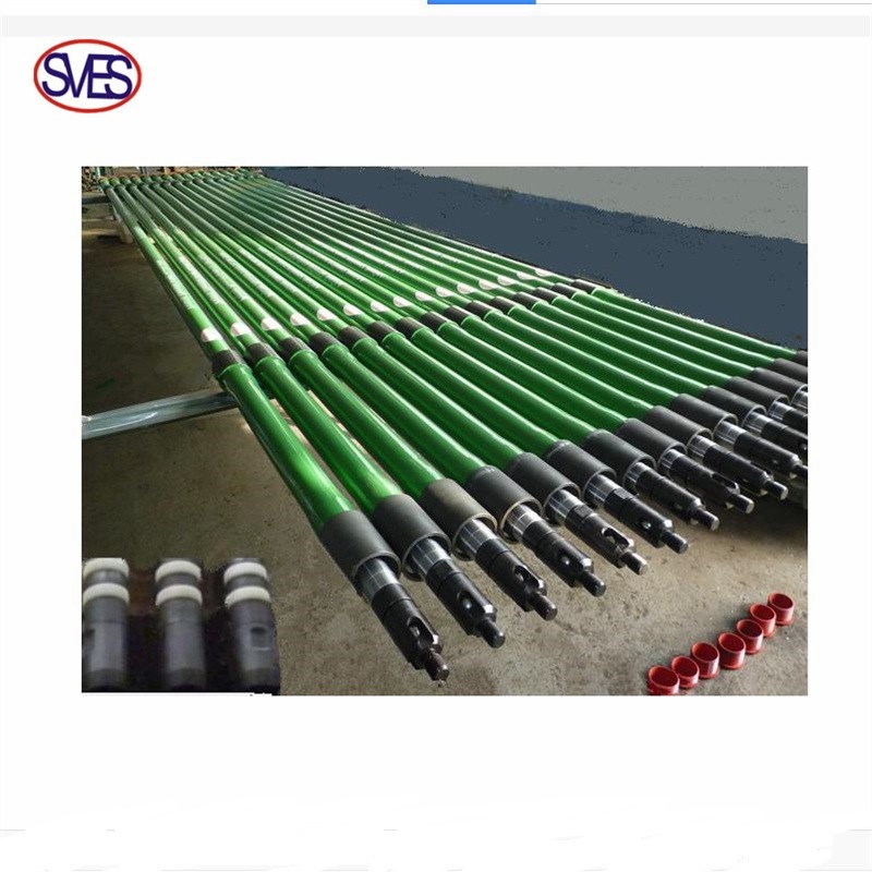
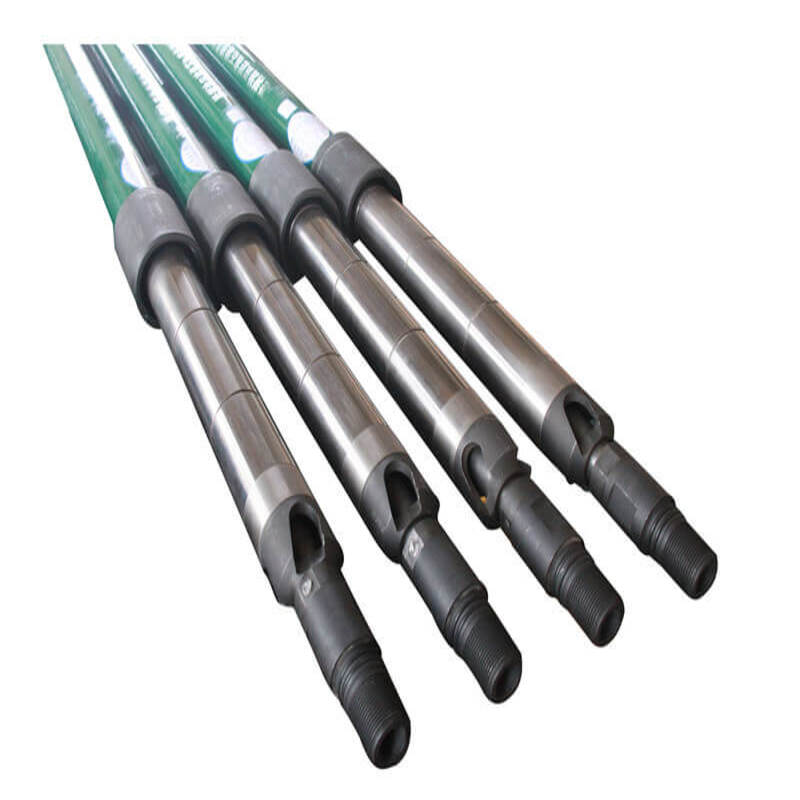
The tubing pump is divided into two types:fishable type(THC and THM) and non-fishable type(THD).
Structural Characteristics:
The tubing pump is structurally robust and consists of pump barrel plunger, an oil drain (optional), standing valve, and extension nipple.
The pump barrel is installed at the bottom of the tubing, the standing valve is installed under the pump barrel, the plunger is connected to the sucker rod, and the entire plunger is placed in the pump barrel, above the standing valve.
Working Principle:
When the pumping unit is in motion, the sucker rod and the plunger are driven to reciprocate linearly in the pump barrel to recovery oil.
When the plunger is running on the stroke, under the action of the gravity of the liquid column in the oil pipe, the traveling valve is closed, and the pressure in the pump barrel below the plunger is lowered, and the standing valve is opened under the action of the oil pressure in the annular cavity of the casing.
The oil enters the cavity created by the upward movement of the plunger.
When the plunger is stroked down, the standing valve is closed, and the pressure inside the pump barrel under the plunger increases.
The traveling valve is opened, so that when the plunger is stroked, the well fluid passing through the standing valve passes through the cavity of the traveling valve and the plunger during the down stroke, into the annular cavity between the sucker rod and the oil pipe above the plunger.
On the next upstroke, these well fluids are lifted together with the remaining well fluid in the annular cavity of the tubing and sucker rods. In fact, only the upstroke is lifted.
Applicable condition:
1.Sand content in well fluid ≤0.2%
2.he total salinity dissolved in the well fluid does not exceed 10000mg/L or the chloride does not exceed 6000mg/L, the hydrogen sulfide content is less than 10ppm, and the carbon dioxide content is less than 250ppm.
3.Gas-liquid ratio ≤60m3/m3, well deviation ≤30°
4.Ban touching pumps
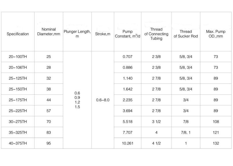
| Pump code | 25-106TH | 25-125TH | 25-150TH | 25-175TH | 25-200TH | 25-225TH | 30-250TH | 30-275TH | 40-325TH | 40-375TH |
| Basic pump diameter | 1 1/16 | 1 1/4 | 1 1/2 | 1 3/4 | 2 | 2 1/4 | 2 1/2 | 2 3/4 | 3 1/4 | 3 3/4 |
| -27 | -31.8 | -31.8 | -44.5 | -50.8 | -57.2 | -63.5 | -69.9 | -82.6 | -95.3 | |
| Plunger length | ≤26(7925) | |||||||||
| Pump barrel length | ≤34(10363) | |||||||||
| Stroke ft (mm) | ≤32(9754) | |||||||||
| Connecting tubing thread | 2 7/8 NU(EU) | 3 1/2 NU(EU) | 4NU | 4EU | ||||||
| Connecting sucker rod thread | 3/4 in | 7/8 in | 1 in | |||||||
| Theoretical displacement | 0.824 sn | 1.140 sn | 1.642 sn | 2.235 sn | 2.918 sn | 3.694sn | 4.560 sn | 5.518 sn | 7.707 sn | 10.261 sn |
| Maximum outer diameter (mm) | 3.5 | 3.5 | 3.5 | 3.5 | 3.5 | 3.5 | 4.25 | 4.25 | 4.5 | 4.6 |
| -88.9 | -88.9 | -88.9 | -88.9 | -88.9 | -88.9 | -108 | -108 | -114.3 | -117 | |
After being assemblied on the surface, the rod pump is run into the well and seated inside the seating nipple. There is no need to lift the tubing, which reduces operation time and cost, frequency of turning on and off tubing threads, and prolongs run life of the tubings.
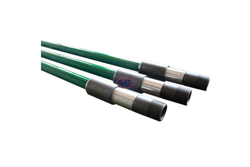
The plunger and the pump barrel are assembled into one body, and is inserted into the oil pipe with the sucker rod.
There are fixed barrels and movable barrels.According to the position of the support assembly, it is divided into two types: the top fixed and the bottom fixed.
According to the support assembly types, it is divided into cup type and mechanical type.
Compared with the tubing pump, the rod type pump has the characteristics of not having to take off the oil pipe when the pump is down, and has a large variety of options.Easiness to operate, saving more than half of the operating time can greatly reduce operating costs, suitable for deep well use.
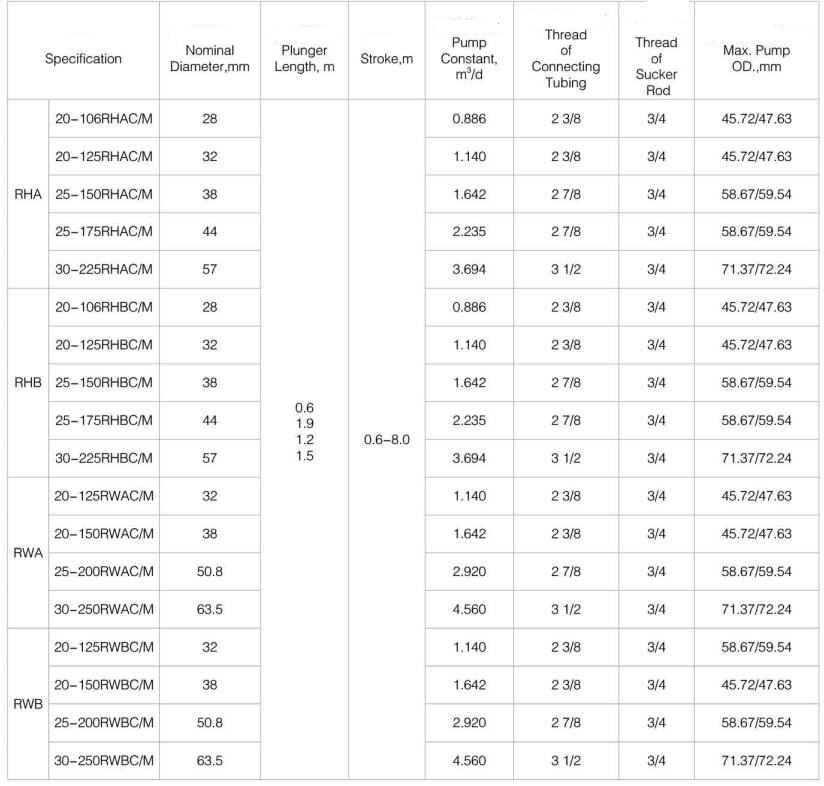
| Standard rod pump specifications | |||||||
| Specification model | Technical Parameter | ||||||
| Type | Model | Pump diameterin(mm) | Plunger length ft(mm) | Barrel length ft(mm) | Connecting tubing thread (in) | Connecting sucker rod thread (in) | Pump constant |
| Mechanical support top fixed thick wall rod pump | 20-125RHAM | 1.25(31.75) | 2~24(609~7315) Increment per foot | 4~34(1219~10363) Increment per foot | 2 3/8 NU/EU | 3/4in | 1.14 |
| 25-150RHAM | 1.5(38.1) | 2 7/8 NU/EU | 3/4in | 1.642 | |||
| 25-175RHAM | 1.75(44.45) | 2 7/8 NU/EU | 3/4in | 2.235 | |||
| 30-225RHAM | 2.25(57.15) | 3 1/2 NU/EU | 3/4in | 3.694 | |||
| Mechanical support bottom fixed thick wall rod pump | 20-125RHBM | 1.25(31.75) | 2 3/8 NU/EU | 3/4in | 1.14 | ||
| 25-150RHBM | 1.5(38.1) | 2 7/8 NU/EU | 3/4in | 1.642 | |||
| 25-175RHBM | 1.75(44.45) | 2 7/8 NU/EU | 3/4in | 2.235 | |||
| 30-225RHBM | 2.25(57.15) | 3 1/2 NU/EU | 3/4in | 3.694 | |||
| Cup support top fixed thick wall rod pump | 20-125RHAC | 1.25(31.75) | 2 3/8 NU/EU | 3/4in | 1.14 | ||
| 25-150RHAC | 1.5(38.1) | 2 7/8 NU/EU | 3/4in | 1.642 | |||
| 25-175RHAC | 1.75(44.45) | 2 7/8 NU/EU | 3/4in | 2.235 | |||
| 30-225RHAC | 2.25(57.15) | 3 1/2 NU/EU | 3/4in | 3.694 | |||
| Cup support bottom fixed thick wall rod pump | 20-125RHBC | 1.25(31.75) | 2 3/8 NU/EU | 3/4in | 1.14 | ||
| 25-150RHBC | 1.5(38.1) | 2 7/8 NU/EU | 3/4in | 1.642 | |||
| 25-175RHBC | 1.75(44.45) | 2 7/8 NU/EU | 3/4in | 2.235 | |||
| 30-225RHBC | 2.25(57.15) | 3 1/2 NU/EU | 3/4in | 3.694 | |||
| Mechanical support top fixed thin wall rod pump | 20-125RWAM | 1.25(31.75) | 2 3/8 NU/EU | 3/4in | 1.14 | ||
| 20-150RWAM | 1.5(38.1) | 2 3/8 NU/EU | 3/4in | 1.642 | |||
| 25-200RWAM | 2(50.8) | 2 7/8 NU/EU | 3/4in | 3.694 | |||
| 30-225RWAM | 2.5(63.5) | 3 1/2 NU/EU | 3/4in | 4.56 | |||
| Mechanical support bottom fixed thin wall rod pump | 15-125RWBM | 1.25(31.75) | 1.900 NU/EU | 5/8in | 1.14 | ||
| 20-125RWBM | 1.25(31.75) | 2 3/8 NU/EU | 3/4in | 1.14 | |||
| 20-150RWBM | 1.5(38.1) | 2 3/8 NU/EU | 3/4in | 1.642 | |||
| 25-200RWBM | 2(50.8) | 2 7/8 NU/EU | 3/4in | 3.694 | |||
| 30-225RWBM | 2.5(63.5) | 3 1/2 NU/EU | 3/4in | 4.56 | |||
| Cup support top fixed thin wall rod pump | 20-125RWAC | 1.25(31.75) | 2 3/8 NU/EU | 3/4in | 1.14 | ||
| 20-150RWAC | 1.5(38.1) | 2 3/8 NU/EU | 3/4in | 1.642 | |||
| 25-200RWAC | 2(50.8) | 2 7/8 NU/EU | 3/4in | 3.694 | |||
| 30-225RWAC | 2.5(63.5) | 3 1/2 NU/EU | 3/4in | 4.56 | |||
| Cup support bottom fixed thin wall rod pump | 15-125RWBC | 1.25(31.75) | 1.900 NU/EU | 5/8in | 1.14 | ||
| 20-125RWBC | 1.25(31.75) | 2 3/8 NU/EU | 3/4in | 1.14 | |||
| 20-150RWBC | 1.5(38.1) | 2 3/8 NU/EU | 3/4in | 1.642 | |||
| 25-200RWBC | 2(50.8) | 2 7/8 NU/EU | 3/4in | 3.694 | |||
| 30-225RWBC | 2.5(63.5) | 3 1/2 NU/EU | 3/4in | 4.56 | |||
| Moving barrel bottom fixed thin wall rod pump | 15-125RWT | 1.25(31.75) | 1.900 NU/EU | 5/8in | 1.14 | ||
| 20-125RWT | 1.25(31.75) | 2 3/8 NU/EU | 3/4in | 1.14 | |||
| 20-150RWT | 1.5(38.1) | 2 3/8 NU/EU | 3/4in | 1.642 | |||
| 25-200RWT | 2(50.8) | 2 7/8 NU/EU | 3/4in | 3.694 | |||
| 30-225RWT | 2.5(63.5) | 3 1/2 NU/EU | 3/4in | 4.56 | |||
| Fixed barrel bottom fixed thick wall rod pump | 20-125RXT | 1.25(31.75) | 2 3/8 NU/EU | 3/4in | 1.14 | ||
| 20-150RXT | 1.5(38.1) | 2 3/8 NU/EU | 3/4in | 1.642 | |||
| 25-200RXT | 2(50.8) | 2 7/8 NU/EU | 3/4in | 3.694 | |||
Compared with the tubing pump, the rod-type oil well pump has the characteristics of no need to set up and down the tubing when lifting the pump, and a wide choice of various forms.
It is easy to check the pump and save more than half of the operating time, which can greatly save operating costs and is suitable for deep well use.
Rod pump can be further optimized by selecting the metallurgy and coating of various components to maximize pump life in specific well conditions.
Type A Rod Pump
pumps are heavy wall, stationary barrel, top anchor design insertable pumps. Available with either 3 cup type hold down (RHAC) or with a mechanical lock hold down (RHAM), RHA pumps allow a greater operating depth due to their heavy wall barrel. Insertable pumps can be removed from the well without having to remove the production tubing. Top anchor design means ideal for sandy wells.
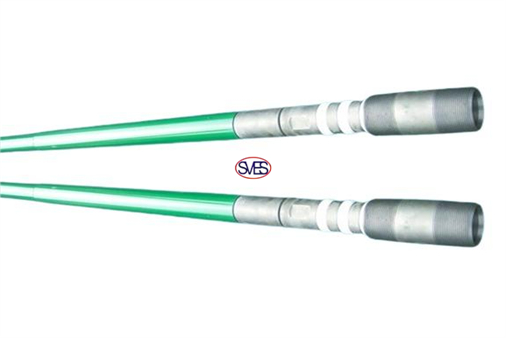
An all-metal plunger pump, the type RH rod pump offers heavy-duty construction. The barrels are made from 3/16-in. wall tubing and are externally threaded, which provides extra strength and permits spacing the pump so that the plunger can stroke out both ends of the barrel. This stroke-through design combats buildup of scale on the inside of the pump barrel.
insert pumps are heavy-walled,stationary barrel, top anchor pumps recognized by as a standard design. These pumps are suitable for moderate depths with high sand fallback on well shutdown. Fluid dispersion directly above the seat nipple prevents the pump from becoming stuck in such a situation.
The Type A rod pump is widely used in petroleum recovery.
The locking device is located at the top. When the plunger moves, the sand around the locking device can be washed away to prevent the sand card, being easy to operate.
The pump can swing around the pivot point of the top locking device.
When the pumps position in the inclined well, the oil pipe and pump barrel are not damaged, the pump is slightly larger than that of the bottom fixed rod pump in the same fixed position, which is more suitable for low-yield and low-surface wells, and the top fixing device makes the pump itself have gas anchoring effect and can be used in oil wells with more gas.
| Pump type | Pump diameter | ||||||
| 31.75 | 38.1 | 44.45 | 50.8 | 57.15 | 63.5 | ||
| RHA | Down pump depth(m) | 2537 | 2532 | 1810 | 1254 | ||
| RHA | Down pump depth(m) | 2099 | 1799 | 1172 | 966 | ||
Application: oil wells with a viscosity around 400mPa-s.
Type B Rod Pump
SVES Oilfield Supply Co., LRHBC Rod Pumptd has developed the downhole pumps with various processes of bronzing, nitriding, chrome plating, tungsten plating for special well conditions.
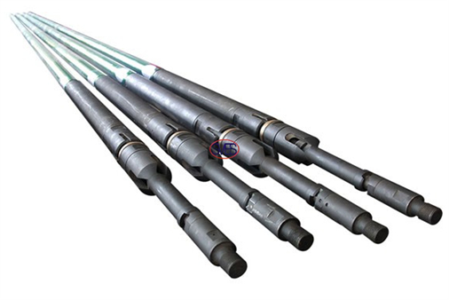
The Type B Rod Pump has the following characteristics.
The locking device is located at the bottom, which has the characteristics that the pump barrel will not be elongated due to the action of the liquid column, only subject to external pressure, and the gap will not increase.
Therefore, it is suitable for use in deep wells; the pump can swing around the pivot point of the bottom locking device and can also be used in inclined wells.
Application: deep wells with viscosity below 400mPa-s
Not applicable: It is easy to deposit sand particles in the annular space of the fixed support sleeve and the bottom locking device, which makes the pump operation difficult, and should not be used in the sand-containing well; the bottom is fixed, the pump barrel swings greatly during operation, and the valve stem and the guide sleeve are intensified.
Wear is not suitable for long stroke pRHBM Rod Pump umps.
The RHBC model features a cup seating assembly.
The RHBM model features a metal seal that can be re-seated several times without replacement.
The RHBC and RHBM pumps are recommended for the following applications:
| Pump type | Pump diameter | ||||||
| 31.75 | 38.1 | 44.45 | 50.8 | 57.15 | 63.5 | ||
| RHB | Down pump depth(m) | 2895 | 2891 | 2231 | 1449 | ||
| RWB | Down pump depth(m) | 2539 | 2216 | 1326 | 1008 | ||
• Wells with low static-fluid levels
• Deep wells
• Gaseous wells (when pump is run in conjunction with a good oil-gas separator or
gas anchor)
• Wells that might pound fluid
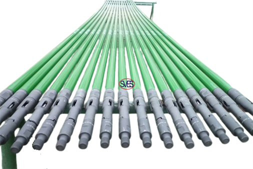
These pumps are not designed to run in sandy wells but can be modified for such duty, using a top-seal assembly or a bottom discharge valve.
The stationary-barrel design is superior to traveling-barrel versions for low fluid levels because the fluid to be pumped has only to pass the larger standing valve located immediately above the shoe.
This design maximizes recovery and minimizes the tendency to foam.
insert pumps are heavy-walled,stationary barrel, bottom hold down pumps recognized
These pumps are recommended for depths of 8,000ft or greater when there is little chance of sand accumulation.
If sand is an issue, nonstandard accessories such as a top seal can be used to prevent a stuck pump.
These pumps can also be modified for use as a stoke through pump to release sand and other material.
To minimize damage to the plunger and barrel, a grooved-body plunger is often used to catch and carry the sand away from those components.
Seating options on this pump include mechanical or cup types suitable for high temperatures and mechanical types to simplify well maintenance.
A mechanical hold-down does not require repair unless major damage has occurred, whereas cups should be replaced every time the pump is unset.
Both hold-down types follow the same procedure of setting by placing the weight of sucker rods down on the pump and unsetting by lifting them up.
Type T Rod Pump
The type T Rod Pump has the following characteristics:
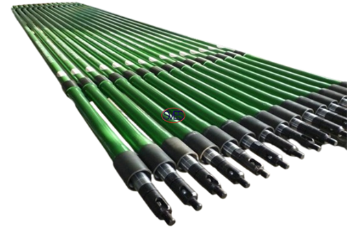
The locking device is located at the bottom. When working, the plunger is fixed and the pump barrel moves up and down.
The well fluid can be stirred continuously and the sand is not easy to deposit on the locking device to generate the card pump.
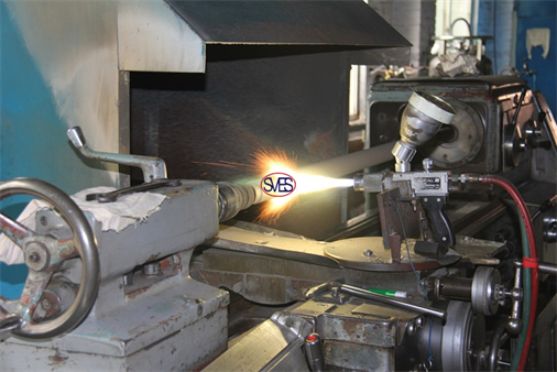
When the pumping well is stopped, the top valve ball closes the valve seat, and the sand in the oil pipe does not deposit in the pump to generate the card pump; the fixed valve and the oil discharge valve are both open valve covers, and the local resistance of the fluid is small, which is favorable for the discharge of the well liquid containing more sand.
Applicable: sand wells with viscosity below 400mPa-s
Not applicable: Due to the poor stability of the pump rod, it is not suitable to use long stroke pump and use in heavy oil wells.
Recommended for shallow operating depths, insert pumps are thin-walled, traveling barrel, bottom hold-down pumps recognized by as a standard design.
Whereas the plunger assembly is attached to the hold-down where it becomes stationary, the barrel assembly is the traveling portion that moves with the sucker rod string.
Because the barrel assembly moves, sand and scale can accumulate around the hold-down without sticking the pump; upon restarting operation, all settled material will be dispersed in the fluid.
The exit point for fluid is through an open three-wing cage, which prevents any solid material from reentering the pump on well shutdown and lengthens the run life of internal components.
Recommended for shallow operating depths, insert pumps are thin-walled, traveling barrel, bottom hold-down pumps recognized by as a standard design.
Whereas the plunger assembly is attached to the hold-down where it becomes stationary, the barrel assembly is the traveling portion that moves with the sucker rod string.
Because the barrel assembly moves, sand and scale can accumulate around the hold-down without sticking the pump; upon restarting operation, all settled material will be dispersed in the fluid.
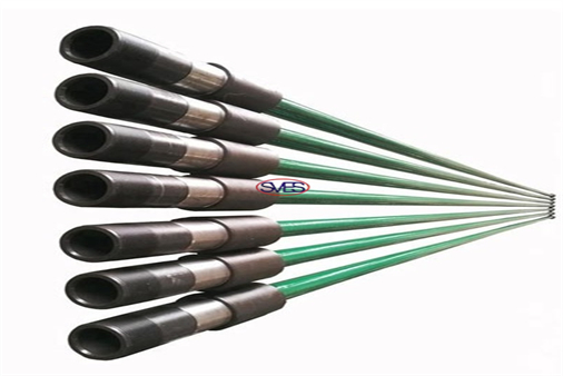
The exit point for fluid is through an open three-wing cage, which prevents any solid material from reentering the pump on well shutdown and lengthens the run life of internal components.
The seating options on this pump include mechanical or cup types suitable for high temperatures, and mechanical types for simplified well maintenance.
A mechanical hold-down does not require repair unless major damage has occurred, whereas cups should be replaced every time the pump is unset. Both hold-down types follow the same procedure of setting and unsetting by placing the weight of the sucker rods down on the pump or lifting up.RWT Rod pump
RWT Rod pumps are thin wall, travelling barrel, bottom anchor design insertable pumps.
Available with either 3 cup type hold down (RWTC) or with a mechanical lock hold down (RWTM), RWT pumps are ideal for wells with high levels of particulates due to their travelling barrel configuration, meaning less chance of the pump becoming stuck in the well.
Insertable pumps can be removed from the well without having to remove the production tubing.
